50% Response rate
Selecting a Pipe end Chamfering Machine starts with the tube, not the sales brochure. Diameter range, wall thickness, material, bevel angle, and production volume shape the choice. A stainless-steel tube can behave differently from mild steel under the same cutting setup. Small differences matter.
The scale of metal production offers useful context. World Steel Association’s World Steel in Figures 2024 reports 1,888.2 million tonnes of crude steel production worldwide in 2023. This is not a pipe-market figure, and it does not measure demand for chamfering machines. It does show the size of the wider steel supply chain. Shigeo Shingo, a pioneering industrial engineer, wrote, “The most dangerous kind of waste is the waste we do not recognize.” His warning applies to end preparation: repeated hand finishing, inconsistent bevels, and avoidable rework can quietly consume production time.
A sound comparison should test real workpieces. Check the machine’s stated capacity against your actual outside diameters and wall thicknesses. Ask for a trial cut, then inspect the bevel, burrs, clamping marks, and repeatability. A smooth edge is not the whole story. Tool-change time, operator access, chip removal, and maintenance also affect daily output. Still, a neat specification sheet can mislead. One practical detail is easy to miss: the best machine for a short production run may not suit continuous, high-volume work. This guide explains how to weigh those trade-offs before choosing a machine.
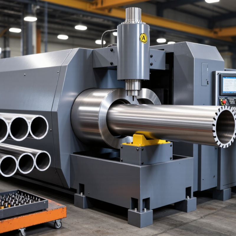
Before comparing machines, identify the exact pipe material. Carbon steel, stainless steel, aluminum, and plastic behave differently under cutting forces and heat. A machine suitable for steel may be too aggressive for thin-wall aluminum or certain plastics. Check the material grade and any coating, too. Coatings can affect tool wear and the finish at the pipe edge.
Measure the pipe’s outside diameter and wall thickness across the actual range you expect to process. A stated diameter capacity does not guarantee that every pipe within that range can be clamped securely. Thin-wall pipe can deform under excess clamping pressure. That matters. Ask how the machine supports the pipe and whether pressure can be adjusted. For thick walls, confirm the available cutting depth and whether the motor can maintain a clean chamfer without excessive vibration.
Use real samples when possible. A short trial can reveal burrs, uneven bevels, or slipping that a specification sheet will not show. Do not guess. Record the material, diameter, wall thickness, and desired chamfer angle for each test. I would also check the result at several points around the rim; one clean spot does not prove the whole edge is consistent. If your pipe sizes vary widely, be candid about the trade-off: one setup may not handle every combination efficiently.
Define the chamfer before comparing machine capacity. Record the angle, face width, root land, and whether the cut is internal, external, or both. ASME B16.25 addresses butt-welding end preparations; use the applicable drawing and specification for the actual dimensions. A generic “45-degree bevel” may still miss the required land or fit-up. Measure the tube’s outside diameter, wall thickness, and material too. Small details matter.
Then estimate real production volume, not just the best-case hourly rate. Count daily parts, batch size, shifts, changeovers, and rejected pieces. The World Steel Association’s World Steel in Figures 2024 reports 1,888.2 million tonnes of crude steel production in 2023, a reminder of the scale of steel processing—not a measure of pipe demand. For a short, mixed batch, quick adjustment and repeatable clamping may matter more than peak speed. For steady, high-volume runs, cycle time, tool life, and loading automation deserve closer scrutiny. Ask suppliers to test your actual pipe sizes and chamfer profile. I would not size from averages alone. A few awkward changeovers can undo a tidy production estimate.
| Required Chamfer Shape | Typical Application | Production Volume Guide | Suitable Machine Setup | Key Selection Checks |
|---|---|---|---|---|
| External chamfer (OD bevel) | Removes the sharp outer edge and prepares the pipe end for handling, fitting, or welding. | Low: occasional batches or fewer than about 100 ends per shift. | Manual or semi-automatic machine for varied jobs and frequent setup changes. | Confirm pipe outside-diameter range, bevel angle, edge consistency, and workpiece clamping method. |
| Internal chamfer (ID bevel) | Creates a bevel on the inside edge, often to improve fit-up or remove an internal sharp edge. | Low to medium: regular batches with moderate changeover requirements. | Semi-automatic machine with tooling matched to the pipe’s inside diameter and wall thickness. | Check access to the bore, minimum inside diameter, chip clearance, and whether the full circumference must be machined. |
| Combined ID and OD chamfer | Finishes both the inner and outer edges of the same pipe end. | Medium: repeated batches, typically around 100–500 ends per shift. | Powered, semi-automatic machine with coordinated tooling or a multi-tool arrangement. | Verify that both chamfers can be produced in one setup and that the specified edge land and angles are maintained. |
| Single-angle bevel for welding | Prepares a pipe end for a specified weld-joint geometry. | Medium to high: recurring production with a stable range of pipe sizes. | Automatic or CNC-controlled machine when repeatable angle and consistent batch output are important. | Match the bevel angle, root face, wall thickness, end squareness, and applicable welding procedure requirements. |
| Compound bevel or other defined profile | Produces a multi-angle or drawing-specific edge profile for a particular joint or assembly. | Varies: select based on repeatability needs and the number of profile changes. | CNC-controlled machine or a dedicated tooling setup for repeatable, specified profiles. | Confirm the complete profile from the drawing, program or tooling changeover needs, and inspection method. |
| Chamfering both pipe ends | Finishes the two ends of each pipe, either in separate operations or in a purpose-built sequence. | High: often more than about 500 ends per shift, depending on pipe size and handling time. | Automatic feeding and handling, or a dual-end configuration where the product range justifies it. | Compare total cycle time, loading and unloading time, pipe length range, end-to-end alignment, and changeover time. |
Planning note: Volume bands are broad selection guides, not guaranteed machine capacities. Actual throughput depends on pipe diameter, wall thickness, material, chamfer dimensions, loading method, tooling changes, and inspection requirements. Confirm the required profile against the part drawing and validate cycle time with representative workpieces.
How to Choose a Pipe End Chamfering Machine
Compare machine types by pipe diameter, wall thickness, and job volume. A portable machine suits field work and short runs; a stationary unit offers a steadier setup for repeated cuts. Manual models can be practical for occasional use, but they demand more operator effort. Check the required chamfer angle and finish against your fitting or welding procedure. A clean, even bevel matters.
Clamping is as important as cutting power. A chain clamp adapts to varied pipe sizes, while a vise or self-centering chuck can hold repeat jobs more consistently. Test the setup on a short offcut: if the pipe shifts or marks easily, the clamp may be wrong for its material or surface. Electric machines avoid dependence on shop air. Pneumatic models can be compact, but air supply and leakage affect their real operating cost. The U.S. Department of Energy’s Improving Compressed Air System Performance sourcebook reports that leaks can waste 20–30% of compressor output. That figure is not a machine-efficiency rating, but it is a useful reminder to check the whole air system.
Tips: Confirm the machine’s capacity, clamp range, and power requirements before ordering. Try a representative pipe section. A neat sample does not guarantee every setup will behave the same.
Use actual pipe outside diameter—not nominal pipe size—to check whether a machine’s clamping range fits your work. The chart shows standard outside diameters for selected NPS pipe sizes.
Selection tip: Portable split-frame machines suit work on installed pipe, while stationary machines are suited to workshop processing. Check whether the machine clamps internally or externally and confirm its stated capacity against the pipe’s outside diameter. Choose electric, pneumatic, or hydraulic power based on site access, available utilities, and required portability.
Pipe outside diameters shown are standard dimensions from ASME B36.10M. Machine capacities and suitable power sources vary by model.
Choosing a pipe end chamfering machine starts with the pipe range you actually process. Check both the smallest and largest diameters, wall thickness, and material. A machine rated for a broad range may still need different clamps or tooling. Ask how long changeovers take, then test one with your typical pipe. A slow setup can erase a fast cutting cycle.
Cutting precision matters at the joint. Look for stable clamping, adjustable feed, and tooling suited to the pipe material. Inspect a sample cut for a consistent bevel, clean edge, and minimal burrs. Use calipers or the specified inspection method; a neat-looking edge can still be uneven. Tool wear changes results. Keep a record of settings and replace inserts when cuts begin to drift.
Safety and ease of use deserve a hands-on check. Guards should shield the cutting area, while controls remain reachable without leaning toward the tool. Confirm how chips are cleared and how the machine is isolated before maintenance. Simple controls help, but training still matters. Ask an operator to load, clamp, cut, and unload a pipe during a trial. Watch for awkward lifting or repeated adjustments. I would not judge the machine from one perfect sample; run several pieces, including a less-than-ideal pipe, and note where the process feels uncertain.
A pipe end chamfering machine should be easy to inspect, clean, and adjust between jobs. Open the maintenance panel and check whether common service points are reachable without removing nearby guards. Look for clear instructions on replacing cutting inserts, setting the chamfer angle, and clearing metal chips. Small delays add up. Ask how often routine checks are required and which parts typically wear first.
Support matters when a machine stops during a scheduled run. Confirm whether technicians can guide operators remotely and how quickly essential spare parts are usually available. Ask for practical training, not just a manual: an operator should be able to spot a dull insert or inconsistent chamfer before rejected parts accumulate. Response times vary. Get the service terms in writing, and check whether troubleshooting materials match the machine’s actual controls.
Compare ownership costs over a realistic production period, rather than looking only at the purchase price. Include tooling, maintenance labor, energy, installation, and expected downtime. For example, estimate the cost of a delayed batch if replacement inserts take several days to arrive. A spreadsheet may still miss unplanned stoppages; that uncertainty deserves attention. Use your own pipe sizes, shift patterns, and changeover frequency when requesting cost estimates, since generic figures can hide the costs that matter most.